MIG welding explained
The Welding Circuit
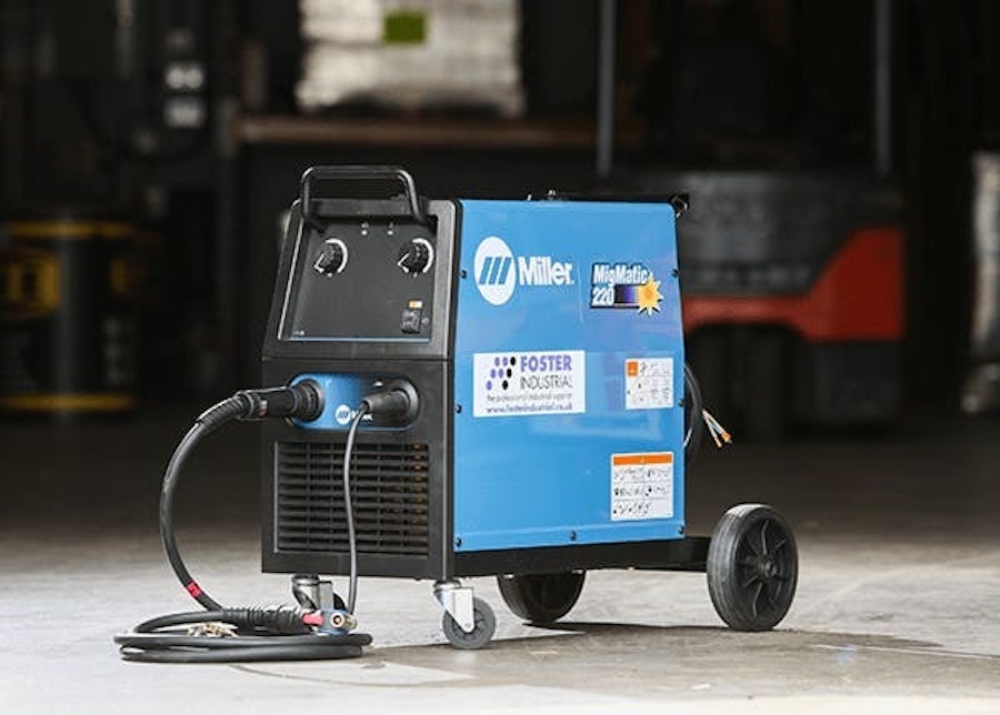
All welding processes work on the principle of a series circuit known as the secondary or welding circuit. A typical layout of the welding circuit is shown below. The circuit consists of a power source, referred to generally as the welding plant, a welding lead referred to as the MIG torch, the workpiece or work bench and a welding return lead and clamp referred to as the earth. In addition to these is a spool of wire and a supply of shielding gas.


The Welding Lead
MIG torch assembly
The function of the welding lead is to bring the power (voltage) available from the machine to create the welding arc. The arc is struck when the continuously fed welding wire electrode comes into contact with the workpiece or joint faces. A typical swan neck torch is shown below. You will see that an integral part of the torch structure is the gas supply tube. The gas supply continues whilst welding is in operation and stops when welding stops.

*From the image above we can see that the torch consists of armored cabling, gas supply, a trigger, a torch liner, a nozzle and a contact tip.
The armored cabling provides protection to the electricity supply and the vehicle for providing the electric supply to the head of the torch. It also allows the gas supply and welding wire to get to their destination which is through and around the contact tip, out of the nozzle and into the weld pool. The trigger, once pressed and held switches everything on, everything being electricity, gas and wire feed. To start welding press and hold the trigger and to stop welding let go of the trigger. Letting go stops everything instantaneously.
The torch liner protects the welding wire during welding and prevents the wire from kinking and misfeeding into the weld pool. Welding wire is ductile and can easily be misshaped by having the welding lead curled up or twisted. The contact tip charges the wire as the wire passes through the hole in the end of the tip. The contact tip is made from copper because copper is a known good conductor of electricity. The contact tip, or more importantly the hole in the end needs to be the same size as the diameter of the welding wire. These come in sizes of diameter 0.6mm, 0.8mm, 1.0mm, 1.2mm, 1.6mm and 2.4mm.
As welding starts the externally supplied gaseous shield starts also. The gas shielding has to be directed locally at the welded joint faces in order to provide a pocket of gas that dispels atmosphere from the joint. Our atmosphere is harmful to the welded joint. The welding wire has two functions; it is the heat source and provides the consumable filler material required to reinforce the welded joint. It comes in the same sizes as the contact tip and must be compatible with the material type (parent metal) being welded i.e. for welding stainless steel a stainless steel wire must be used, for welding aluminum and aluminum wire must be used and for welding carbon steels a carbon steel wire must be used. Something else happens as the trigger is pressed. The rollers within the power source are activated and pull the wire from its reel. They consist of a smooth top roller and a grooved bottom roller plus a mechanism for tensioning the wire. Note that the grooved roller will have two grooves. The groove needs to be the same size as the wire diameter. It is essential for the correct feed of the wire electrode
The welding return lead returns the electric supply to the power source and goes to an approved electrical earth through the machine and its isolation switch. Before reading Lesson 3 about setting up your machine MIG set & making it run to it's optimum, study the features discussed in this article. In addition, remember what you learnt from Lesson 1 about your own protection and in particular electrical safety.
The Power Source
For this process the power source is a rectifier unit. This equipment converts the mains alternating current (AC) electric supply to direct current (DC) supply. In terms of the welding circuit the torch is connected to the positive (+)terminal available generally at the front of the machine and the welding return lead connected to the available negative (-) terminal. This means that the power source provides an electricity supply that is connected as DC electrode positive (DC+ve). Note; an approved electrical earth is provided through the machine and to an approved electrical earth as part of the mains electric supply.


Welding using the MIG process
How it works
The welding arc between a small diameter wire electrode and the metal being welded creates the weld pool. The wire is fed at great speed to produce weld beads at a very fast rate. The gas shield protects the weld from the surrounding air. The process requires less skill than other methods and is easily mechanised Setting up The welding return clamp is attached to the work piece to complete a circuit. The shielding gas is set to a welding pressure of between 15-20 litres/min. It is important that the contact tip is selected to suit the wire diameter. The wire diameter increases when welding thicker materials The wire feed speed controls both the rate at which wire is fed and varies the current used. The voltage burns off the wire and increases or decreases the length of the arc. The setting of the wire feed and voltage must be in balance in order to achieve a satisfactory weld.
Welding technique
For a right handed person, the welding torch is pointed forwards at an angle of 70º-80º in the direction you want to weld. The arc length should be kept at approximately 5mm from the weld pool. The speed of travel must be constant to attain a satisfactory weld size.
The four types of MIG welding:
- Dip transfer is typically used on small diameter fabrications. The voltage is kept low & the weld ball size small.
- Globular welding uses more amps and generates spatter. Globular is prevalent when MIG equipment is used on the wrong settings.
- Spray transfer is used on heavier plate when the voltage settings are higher and offers a smoother weld.
- Pulse MIG is generally used for the welding of stainless or aluminium fabrications. Lower heat input means less distortion, lower fume generation and spatter free welding.


Shop Mig Welding
Shop Featured Equipment
Shop Our Services
01509 509269


